

How to match LED drivers to dimming controls without flicker
A lighting system can look stable during bench testing and begin to flicker only after installation: lights may pulse at low output, drop out near the bottom of the dimming range, flash when a control is adjusted, or refuse to turn fully off. In most cases, the fixture is not simply “bad.” The problem is a mismatch between the LED driver, the dimming control, the connected LED load, or the wiring environment.
The practical rule is to match the dimming method first, then verify the driver’s output characteristics, supported load range, control limits, and installation conditions. A driver marked “dimmable” is not automatically compatible with every dimmer. Flicker-free operation depends on the complete circuit: control, driver, LED module, wiring, and sometimes the number of fittings connected to one control channel.
Start with the dimming interface, not the fixture wattage
The first selection question is: what signal does the control send, and what signal does the driver expect? Drivers and controls may both use the word “dimming” while operating in entirely different ways. Connecting incompatible methods can cause unstable output, limited dimming, audible noise, permanent damage, or no response at all.
Phase-cut dimming deserves particular care because it is often used in retrofit environments where an existing wall dimmer is retained. A leading-edge dimmer and a trailing-edge dimmer alter the mains waveform differently. Some LED drivers tolerate one type but not the other. Even when a driver states phase-cut compatibility, it may have a preferred dimmer type or a tested-control list. That information is more useful than a generic “dimmable” label.
With 0–10 V systems, a frequent error is treating the control terminals as if they were interchangeable with mains switching terminals. They are not. The driver may source or sink a control current depending on its design, and the controller must be able to work with that arrangement. DALI requires another level of verification: bus topology, power supply arrangements where applicable, addressing, grouping, and the control system’s commissioning process can all affect apparent dimming behavior.
Read the driver data as a compatibility document
Once the interface is confirmed, examine the electrical limits that define whether the driver can regulate the connected LEDs properly. This is where nominal wattage alone becomes misleading.
Constant-current drivers are designed to maintain a stated output current across a specified voltage range. The LED module or series string must operate within that range. A driver rated at the right wattage can still be unsuitable if its output current is too high, too low, or if the LED forward voltage falls outside the driver’s operating window. Current mismatch can alter light output, color behavior, thermal stress, and dimming stability.
Constant-voltage drivers, commonly used with LED strips and some modular systems, provide a fixed output voltage such as 12 V or 24 V. The LED load must require that same nominal voltage, and total load must remain within the usable operating range. A dimming controller may sit on the input side of the power supply, on the output side between supply and load, or be integrated into the driver. These arrangements are not interchangeable.
Look for the following details in the driver documentation:
- Input voltage and frequency range.
- Output type: constant current or constant voltage.
- Rated output current or voltage and allowable adjustment range.
- Minimum and maximum output voltage for constant-current operation.
- Rated power and any stated minimum load.
- Supported dimming protocols and any restrictions by control type.
- Minimum dimming level and whether dim-to-off is supported.
- Maximum number of drivers allowed on one control channel.
- Inrush current, power factor, and control-input current where relevant.
- Temperature limits, enclosure conditions, and required derating.
The bottom end of the dimming range is often where hidden incompatibility appears. One driver may dim smoothly to a very low level, while another reaches a threshold and abruptly turns off. A control designed for deep dimming cannot force a driver below its stable regulation point. Conversely, a driver capable of dim-to-off may still remain faintly energized if the control system does not send the necessary command or if leakage current is present in the circuit.
Calculate the actual load, including its operating behavior
For a constant-voltage installation, add the power of all connected LED loads on the driver output and compare it with the driver’s allowed load range. Leaving reasonable operating margin is usually preferable to running at the edge of the rating, especially where ambient temperature is elevated or the system operates for long periods. The driver’s stated output rating is not a guarantee that every load level will dim equally well.
For constant-current systems, calculate the total forward voltage of the LED modules in series at the specified drive current. It must remain inside the driver’s rated voltage range, not merely near it under one temperature condition. LED forward voltage changes with temperature and manufacturing tolerance. A string that barely fits the driver range may behave inconsistently during start-up or at reduced levels.
Phase-cut systems require one more calculation: the total driver load seen by the dimmer. Traditional dimmers were designed around resistive or magnetic loads and may need a larger load to regulate reliably. LED drivers draw power electronically, often with high inrush current and non-linear waveform characteristics. A dimmer may therefore operate poorly even when its printed wattage rating appears sufficient. Its stated LED load rating, minimum load requirement, and permitted number of electronic drivers matter more than the equivalent incandescent rating.
Symptoms can point to the part of the mismatch
Flicker is a visible symptom, but its timing helps narrow the cause. Random flicker at a fixed setting is different from flicker that occurs only while the slider moves. A short diagnostic observation before replacing components can prevent unnecessary rework.
A useful isolation test is to operate one known-compatible driver and load from the proposed control, then add devices incrementally. If the first unit is stable but problems begin as more drivers are added, the issue may be control loading, inrush current, or the number of devices on the channel. If one unit behaves poorly by itself, inspect the driver model, LED load, wiring termination, and control configuration before assuming the whole system needs redesign.
Set up the control range after the hardware is matched
Compatible hardware can still flicker when the control has not been adjusted. Many phase-cut dimmers provide low-end and high-end trim settings. The low-end setting should be raised until the connected LEDs maintain stable light without pulsing or dropping out. The high-end setting may need adjustment if the lamps flash, surge, or fail to reach a consistent maximum at the top of the control range.
Digital systems require commissioning rather than mechanical trimming. DALI drivers may have configurable minimum levels, fade times, scenes, and power-on behavior. An inappropriate minimum-level setting can make a driver appear defective when it is simply being commanded below the stable range of the connected LED module. Analog 0–10 V controls may also need calibration, particularly when a control system maps user interface percentages to an output signal range that does not align with the driver’s response curve.
Do not judge dimming quality only by whether the lights turn on and off. Evaluate the full travel of the control: start-up from off, smoothness through the lower range, repeatability at the same setpoint, behavior when several zones operate, and recovery after power interruption. In spaces where cameras, inspection equipment, or rotating machinery are present, visually subtle modulation may still be operationally significant. The driver’s stated flicker performance and the application’s sensitivity should be reviewed together.
Wiring practices that protect a compatible design
Correctly specified LED drivers can become unstable through poor installation practice. Keep mains conductors and low-voltage control wiring separated where the system design requires it. Long control runs, incorrect polarity, loose terminals, and poorly terminated bus connections can introduce intermittent faults. For DALI and other digital control buses, follow the permitted cable type, voltage-drop considerations, topology rules, and device limits specified for that system.
In phase-cut circuits, do not mix unrelated driver types on one dimmer merely because their wattage totals are within the rating. Different input circuits can react differently to the chopped waveform. One driver may remain stable while another causes the dimmer to lose regulation for the whole group. Where mixed fixture types are unavoidable, separate control channels are often easier to validate than trying to make one dimmer serve every load.
Thermal conditions also affect behavior. A driver installed in a confined ceiling void, enclosure, or high-temperature luminaire may reduce output or enter protection behavior as it heats up. What looks like flicker can be thermal cycling. Confirm driver case-temperature limits, ventilation, mounting method, and the actual load before treating the dimming control as the only suspect.
A practical approval sequence before ordering
For a new installation or a replacement program, approve the combination rather than approving each component separately. Record the exact driver part number, dimming interface, control model, LED load configuration, number of drivers per channel, expected cable arrangement, and intended minimum light level. Revision differences matter; two drivers with similar names may not use identical dimming circuitry.
- Identify the control protocol required by the building or application.
- Select LED drivers that explicitly support that protocol.
- Confirm constant-current or constant-voltage output matches the LED load.
- Check electrical operating ranges, including low-load and low-dim behavior.
- Verify channel capacity, inrush limits, and the number of drivers permitted per control.
- Test the exact combination across the intended dimming range before broad installation.
- Document control settings or commissioning parameters so replacement work does not change system behavior.
When flicker persists after protocol, load, and settings have been checked, measurement may be necessary. A qualified electrical professional can verify supply conditions, grounding, waveform behavior, control signal integrity, and thermal operation. This is especially important where the circuit serves critical work areas, where several drivers fail in the same pattern, or where electrical changes are being considered. The fastest route to stable lighting is usually not changing parts at random, but confirming where the driver, control, load, and installation assumptions stopped matching.
 When an export market analysis platform can validate demand in a new marketExport market analysis platform insights help validate new-market demand through buyer fit, regulations, logistics, competition, and profitable entry conditions.
 What is driving the beauty and personal care market in the USA?Beauty and personal care in USA is driven by targeted solutions, selective premiumization, digital discovery, clean-label trust, diverse needs, and compliance. Explore key growth opportunities.
 How trade flow monitoring reports reveal changing regional demandTrade flow monitoring reports reveal changing regional demand through import volumes, sourcing shifts, product mix, logistics signals, and regulatory trends. Explore actionable market insights.
 How international market intelligence for investors reduces market-entry riskInternational market intelligence for investors reduces market-entry risk by validating demand, regulations, logistics, and competition before capital is committed.
 How international sourcing intelligence helps identify supplier risk earlyInternational sourcing intelligence helps businesses spot supplier risks early, protect supply continuity, and make smarter global procurement decisions.
 How trade data aggregation analytics reveals emerging supplier marketsTrade data aggregation analytics reveals emerging supplier markets through export trends, input flows, logistics, and regulatory signals. Discover smarter sourcing insights.
 What industrial cluster monitoring in Vietnam reveals about site riskIndustrial cluster monitoring Vietnam reveals hidden site risks across labor, utilities, logistics, compliance, and supplier dependencies. Make smarter sourcing and expansion decisions.
 Food Technology Trends Reshaping Shelf Life, Safety, and Product InnovationFood technology is reshaping shelf life, safety, and innovation. Discover the trends helping food businesses cut risk, improve compliance, and unlock stronger global market growth.
 How electronics manufacturing services are changing with low-volume demandElectronics manufacturing services are evolving fast with low-volume demand. Learn how agile EMS partners improve flexibility, compliance, sourcing resilience, and speed to market.
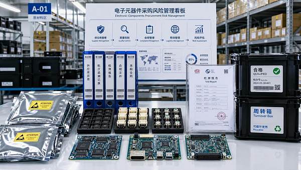
 How Can Buyers Reduce Procurement Risks for Electronic Components?How to reduce procurement risks for electronic components: learn how buyers assess traceability, lead times, compliance, and supplier types to avoid costly sourcing mistakes.
 What Sourcing Intelligence India Reveals About Supplier Risk and Cost ShiftsSourcing intelligence India reveals hidden supplier risk, compliance gaps, logistics pressure, and real cost shifts—helping buyers compare vendors smarter and source with more confidence.
 Fashion Trends 2026: Which Materials, Colors, and Silhouettes Are Gaining Ground?Fashion trends 2026 spotlight tactile fabrics, mineral colors, and controlled volume. Explore the materials, shades, and silhouettes shaping smarter, more wearable style.
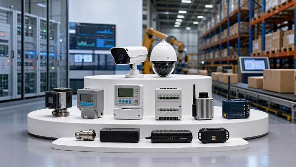
 Smart Device Market Outlook: Key Growth Drivers, Segments, and Business OpportunitiesSmart device market trends are shifting toward system value, industrial demand, and resilient supply chains. Explore key growth drivers, high-potential segments, and business opportunities.
 How Global Trade Intelligence Services Help B2B Firms Evaluate Markets and SuppliersGlobal trade intelligence services help B2B firms compare suppliers, assess market potential, and uncover compliance, logistics, and pricing risks before costly decisions are made.
 Manufacturing Sector Updates for Investors: What Signals Matter Most in 2025?Manufacturing sector updates for investors in 2025: track orders, margins, supply chains, regulation, and exports to spot resilient manufacturers and smarter investment signals.
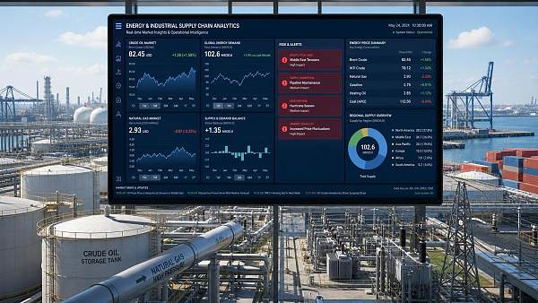
 How Energy Market Intelligence Helps Businesses Track Price Risks and Demand ShiftsEnergy market intelligence helps businesses spot price risks, demand shifts, and supply pressure early—improving procurement, resilience, and faster strategic decisions.
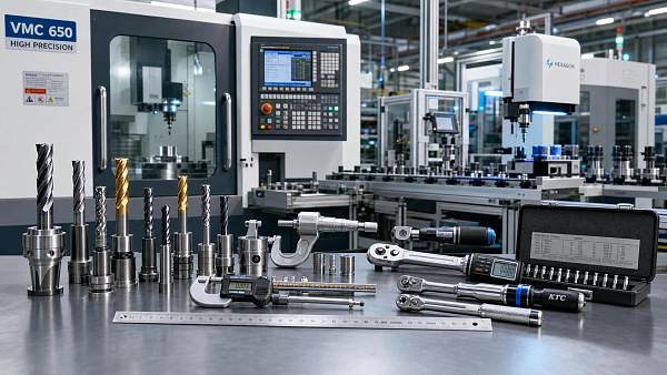
 Precision Hardware Tools Market: Key Demand Drivers, Segments, and Growth OutlookPrecision hardware tools market trends are reshaping sourcing, compliance, and automation. Explore key demand drivers, segment shifts, regional supply patterns, and growth opportunities.
 How to Use Customs Import Data to Find Buyers, Track Competitors, and Spot Demand?Customs import data helps you find real buyers, track competitors, and spot demand shifts early. Learn practical ways to turn trade records into smarter global business decisions.
 Manufacturing Cost Analysis: 8 Cost Drivers That Change Your Unit PriceManufacturing cost analysis explained through 8 key cost drivers that impact unit price, supplier stability, and margins—learn how to compare quotes smarter and reduce sourcing risk.
 Industrial Market Realities: What Buyers Should Check Before Comparing Supplier QuotesIndustrial market realities shape every supplier quote beyond unit price. Learn what to check on compliance, lead times, logistics, and hidden cost risks before comparing offers.
 Beverage Production Line Planning: Key Equipment, Capacity, and Hygiene RequirementsBeverage production line planning made practical: discover key equipment, real capacity sizing, and hygiene requirements to improve efficiency, safety, and long-term plant performance.













Global Trade Insights & Industry
Our mission is to empower global exporters and importers with data-driven insights that foster strategic growth.
Search News
Popular Tags
Industry Overview
The global commercial kitchen equipment market is projected to reach $112 billion by 2027. Driven by urbanization, the rise of e-commerce food delivery, and strict hygiene regulations.