

How to identify a failing machine seal during industrial maintenance
How to Identify a Failing Machine Seal During Industrial Maintenance
A failing machine seal can quickly lead to leaks, contamination, unplanned downtime, and costly equipment damage. For maintenance teams responsible for pumps, mixers, gearboxes, hydraulic systems, compressors, and process equipment, early recognition matters more than a quick replacement after a breakdown. A seal is often a small component in a larger assembly, but its condition can reveal problems with alignment, lubrication, pressure control, temperature, shaft condition, or the process fluid itself.
During industrial maintenance, the practical question is not simply whether a seal is leaking. Some applications may permit a small, controlled amount of leakage, while others cannot tolerate any escape of product, lubricant, gas, or wash fluid. The more useful question is whether the seal is operating within the limits expected for that machine and service condition. Identifying the difference requires observation, operating data, and a careful inspection of the surrounding equipment.
Start by Understanding What the Seal Is Protecting
Machine seals serve different purposes. A mechanical seal on a centrifugal pump separates the pumped fluid from the atmosphere around a rotating shaft. A lip seal may retain oil in a gearbox or bearing housing. Hydraulic seals maintain pressure and prevent fluid bypass inside cylinders, valves, and actuators. Static gaskets and O-rings seal flanges, covers, and fittings where there is no relative movement.
That distinction affects the inspection method. A mechanical seal failure may be linked to shaft runout, dry running, incorrect flush conditions, or pipe strain. A worn rotary lip seal may point to a scored shaft, excessive bearing play, contamination, or incompatible lubricant. An O-ring that has become brittle or swollen may indicate temperature exposure or chemical incompatibility. Replacing the visible failed part without identifying its duty and failure mode often creates a repeat maintenance event.
Before opening equipment, review the machine’s service history: fluid handled, normal pressure and temperature range, recent operating changes, previous seal replacements, lubrication used, and any shutdown or cleaning event that happened before the symptom appeared. This background is especially useful where maintenance records are shared between production, service contractors, and overseas equipment suppliers.
Visible Leakage Is a Signal, Not a Diagnosis
External leakage is usually the first warning sign, but the location and character of the leak matter. A fresh, wet trail at a pump seal chamber suggests an active problem. A dry residue may show that leakage occurred earlier and has since changed with operating conditions. Oil collecting around a gearbox output shaft may come from a lip seal, but it can also result from an overfilled housing, blocked breather, or lubricant being thrown outward by a rotating component.
Look beyond the amount of fluid. Note whether the leakage is clear, darkened, foamy, crystallized, sticky, abrasive, or mixed with another substance. These details help separate a sealing defect from a process or lubrication issue. For example, deposits around a mechanical seal may indicate evaporation or product buildup on the seal faces. Milky oil near a bearing housing can suggest water ingress. Fine particles in leaked fluid may point to wear elsewhere in the system.
Leakage that appears only during startup, at high load, or after a temperature change deserves attention even if the machine runs normally for much of the shift. Thermal expansion, pressure cycling, and transient vibration can expose a seal that looks acceptable during a brief idle inspection.
Listen for Changes in Sound and Vibration
A seal does not usually create vibration on its own, but abnormal vibration can damage sealing surfaces or prevent them from tracking correctly. When a pump or rotating machine develops a new hum, rattle, rubbing sound, or periodic vibration, the seal should be checked alongside bearings, couplings, impellers, alignment, and foundation condition.
For maintenance personnel, trend information is more useful than an isolated reading. If vibration monitoring is available, compare current observations with the machine’s established baseline under similar speed, load, and process conditions. A rise in vibration near a seal replacement interval does not prove seal failure, yet it strengthens the case for inspection. Conversely, replacing a mechanical seal while ignoring excessive shaft movement may damage the new seal shortly after restart.
Manual checks also have value when performed safely. Changes in machine noise, visible coupling movement, loose guards, or a shaft that appears to run unevenly should be documented before disassembly. Never use a seal leak as a reason to approach rotating equipment without appropriate guarding, isolation procedures, and site safety controls.
Temperature and Pressure Changes Often Reveal the Cause
Heat is one of the most common contributors to premature seal damage. A seal may overheat because of dry running, insufficient lubrication, poor cooling, high friction at the sealing faces, blocked flush lines, incorrect assembly, or operation outside the intended temperature range. Hot discoloration around elastomeric parts, hardened seal materials, burnt oil odor, or localized heat near the seal area should not be ignored.
Where permitted by site procedures, compare temperatures at comparable points on similar machines or against prior maintenance records. The goal is not to rely on a universal temperature number; acceptable limits depend on equipment design, media, ambient conditions, and manufacturer guidance. A sudden temperature change is often more informative than a single value.
Pressure behavior matters as well. Loss of hydraulic holding pressure, a pump that cannot maintain expected process conditions, frequent topping-up of lubricant, or a system that requires repeated pressure adjustment may indicate an internal or external sealing issue. However, pressure loss can also come from worn valves, damaged hoses, cracked fittings, internal bypass, or process instability. Confirm the leak path before assigning the fault to a seal.
What Removed Seals Can Tell You
A removed seal is evidence. It should be inspected before it is discarded, particularly when the same machine has experienced repeated failures. Record its position, orientation, part marking where available, and the condition of mating parts such as sleeves, shafts, housings, seal faces, and grooves.
These observations are not conclusive on their own. A cracked seal face, for instance, may be the final result of another mechanical problem rather than the original cause. The most reliable assessment connects the part condition with operating records and the condition of the machine around it.
Do Not Miss the Installation and System Factors
Many seal failures begin during installation. A seal can be cut on a sharp keyway, installed dry when lubrication is required, positioned in the wrong direction, compressed incorrectly, or contaminated by debris left in the housing. Mechanical seals are particularly sensitive to handling. Seal faces should be clean, protected from impact, and assembled according to the equipment or seal supplier’s instructions.
Check the mating surfaces rather than assuming that a new seal will compensate for them. Shaft sleeves may be worn where the old seal contacted them. Bearing wear can create radial movement. Misalignment can place loads on a pump shaft that the seal was not designed to absorb. A blocked vent can raise gearbox pressure and force lubricant past an otherwise serviceable lip seal. In process equipment, incorrect flushing, cooling, or barrier-fluid conditions can shorten mechanical seal life.
This is why a maintenance work order should capture more than “seal replaced.” Useful records include leakage location, process fluid, running condition when the issue appeared, observed damage, associated vibration or temperature changes, replacement part reference, and corrective work on surrounding components. Over time, that record makes recurring patterns easier to see.
A Practical Inspection Sequence
When a possible seal problem is reported, an effective sequence is to make the machine safe, confirm the actual leak or performance symptom, review recent operating changes, and inspect accessible areas before dismantling. Check fluid levels, breathers, flush connections, mounting bolts, couplings, guards, and visible shaft areas. Review relevant pressure, temperature, and vibration trends if the site maintains them.
If shutdown and disassembly are necessary, inspect the old seal and the surfaces it worked against. Do not install a replacement until the source of contamination, heat, movement, pressure, or chemical exposure has been considered. After reassembly, monitor the machine during restart rather than treating commissioning as a separate task. Initial leakage, unusual heat, unstable pressure, or noise can reveal an installation issue early enough to prevent more extensive damage.
When a Seal Issue Becomes a Supply and Reliability Issue
For after-sales maintenance teams, seal selection is also a supply-chain decision. A replacement must match more than nominal dimensions. The application may require confirmation of material compatibility, design arrangement, operating medium, shaft or housing condition, availability of mating components, and any customer-specific documentation. In export and cross-border service work, part identification can be complicated by incomplete machine records, superseded references, regional equipment variants, and long lead times for specialized materials.
This is where structured industrial information becomes useful. Global Trade Insights & Industry Network (GTIIN) follows machinery, industrial components, supply-chain developments, procurement conditions, and changing market requirements across multiple sectors. For maintenance and sourcing teams, the value is not simply locating a component category. It is connecting technical replacement needs with supplier-region visibility, delivery risk, material information, and the documentation expectations that may affect an international transaction.
A failing seal should be treated as an early warning from the machine, not merely a consumable part to reorder. Confirm the failure mode, inspect the system that supports the seal, and document what was found. That approach reduces repeat interventions and gives procurement teams a clearer basis for specifying the correct replacement when reliability, service continuity, and cross-border supply conditions all need to be considered.
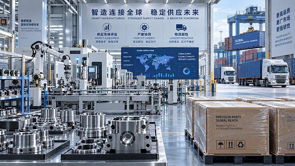
 How to assess Singapore suppliers with global supply chain intelligenceExplore international supply chain intelligence Singapore buyers can use to verify suppliers, assess capabilities and delivery risks, and make confident sourcing decisions.
 Which macroeconomic indicators help forecast U.S. industrial demand?Explore industrial macro analysis USA decision-makers can use to forecast demand. Track new orders, inventories, and credit signals to sharpen procurement and capacity decisions.
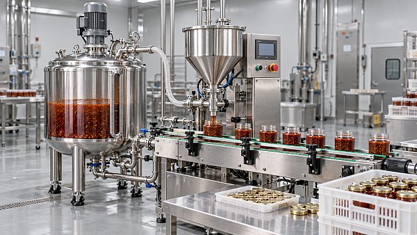
 Can a food processing manufacturer meet your small-batch needs?Can a food processing manufacturer meet your small-batch needs? Discover how to assess minimum orders, costs, packaging, and safety to choose the right partner for your launch.
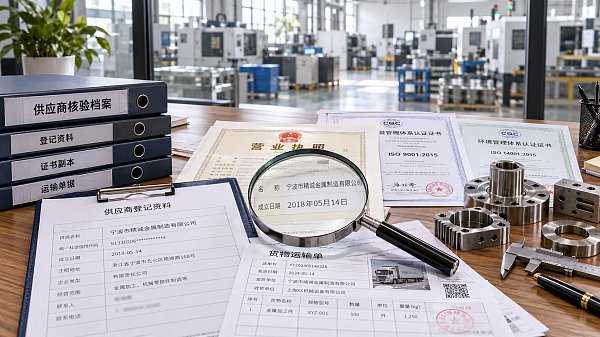
 How to verify sourcing intelligence data before selecting suppliersVerify sourcing intelligence data before choosing suppliers. Learn how to check company records, certifications, and capacity to reduce procurement risk and build a reliable shortlist.
 How to use supplier risk analysis to spot financial warning signsUse supplier risk analysis to spot cash flow pressure, debt risks, and delivery warning signs. Learn practical steps to reduce exposure and protect supply continuity.
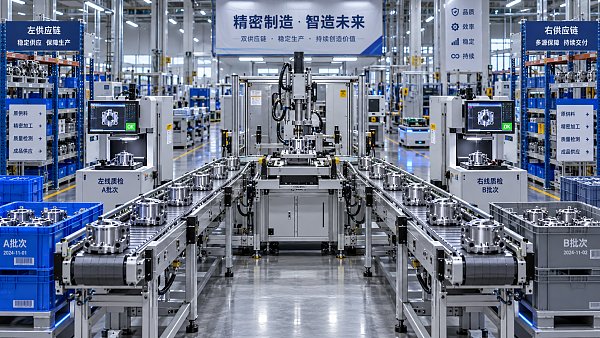
 When dual sourcing makes sense in a sourcing strategy for manufacturersSourcing strategy for manufacturers: learn when dual sourcing strengthens supply continuity, reduces disruption risk, and protects production without adding unnecessary complexity.
 How bulk commodities pricing affects long-term supply contractsBulk commodities pricing shapes long-term supply contracts through index rules, freight, quality, volume, and currency risk. Explore strategies for resilient costs and supply security.
 Which global manufacturing trends by sector matter most for sourcing plans?Global manufacturing trends by sector: identify sourcing risks, supplier resilience, compliance demands, and cost drivers to build smarter, more reliable procurement plans.
 What industrial trade intelligence pricing should include before you subscribeIndustrial trade intelligence pricing explained: compare coverage, data quality, access rights, and workflow value before choosing a subscription that supports smarter trade decisions.
 How an industrial trade intelligence dashboard can identify new supplier marketsDiscover how an industrial trade intelligence dashboard helps identify new supplier markets by comparing capacity, landed cost, logistics resilience, and compliance risk.
 Which global market entry barriers should exporters assess first?Global market entry barriers exporters should assess first: tariffs, compliance, buyer qualification, logistics, and payment risk. Build a practical strategy for confident market entry.
 How trade data aggregation analytics can reveal emerging supplier marketsTrade data aggregation analytics reveals emerging supplier markets by connecting trade flows, capacity signals, logistics, and compliance insights for smarter sourcing decisions.
 When an export market analysis platform can validate demand in a new marketExport market analysis platform insights help validate new-market demand through buyer fit, regulations, logistics, competition, and profitable entry conditions.
 What is driving the beauty and personal care market in the USA?Beauty and personal care in USA is driven by targeted solutions, selective premiumization, digital discovery, clean-label trust, diverse needs, and compliance. Explore key growth opportunities.
 How trade flow monitoring reports reveal changing regional demandTrade flow monitoring reports reveal changing regional demand through import volumes, sourcing shifts, product mix, logistics signals, and regulatory trends. Explore actionable market insights.
 How international market intelligence for investors reduces market-entry riskInternational market intelligence for investors reduces market-entry risk by validating demand, regulations, logistics, and competition before capital is committed.
 How international sourcing intelligence helps identify supplier risk earlyInternational sourcing intelligence helps businesses spot supplier risks early, protect supply continuity, and make smarter global procurement decisions.
 How trade data aggregation analytics reveals emerging supplier marketsTrade data aggregation analytics reveals emerging supplier markets through export trends, input flows, logistics, and regulatory signals. Discover smarter sourcing insights.
 What industrial cluster monitoring in Vietnam reveals about site riskIndustrial cluster monitoring Vietnam reveals hidden site risks across labor, utilities, logistics, compliance, and supplier dependencies. Make smarter sourcing and expansion decisions.
 Food Technology Trends Reshaping Shelf Life, Safety, and Product InnovationFood technology is reshaping shelf life, safety, and innovation. Discover the trends helping food businesses cut risk, improve compliance, and unlock stronger global market growth.
 How electronics manufacturing services are changing with low-volume demandElectronics manufacturing services are evolving fast with low-volume demand. Learn how agile EMS partners improve flexibility, compliance, sourcing resilience, and speed to market.















Global Trade Insights & Industry
Our mission is to empower global exporters and importers with data-driven insights that foster strategic growth.
Search News
Popular Tags
Industry Overview
The global commercial kitchen equipment market is projected to reach $112 billion by 2027. Driven by urbanization, the rise of e-commerce food delivery, and strict hygiene regulations.