

How to size a frequency inverter for an electric motor
Size a frequency inverter primarily by comparing its rated output current with the motor’s nameplate full-load current at the intended connection voltage. Then verify that the drive can supply the current and torque required during starting, acceleration, and the heaviest operating period. Matching the motor’s kilowatt or horsepower rating is a useful starting point, but it is not enough to establish a suitable drive size.
The supply voltage, load type, operating speed, ambient temperature, and installation conditions can all change the selection. A drive that appears correctly rated in a catalog may need a larger frame after derating, while a larger drive alone will not solve a motor cooling problem or an undersized supply.
Start with the motor nameplate and supply
Record the motor’s rated voltage, full-load current, frequency, speed, power, and connection arrangement. For a dual-voltage motor, use the current corresponding to the voltage at which its windings will be connected. A motor connected for the lower voltage draws a higher rated current than it does at the higher voltage; selecting a drive from the wrong nameplate line can produce a substantial sizing error.
Next, establish the available input supply: voltage, phase count, and frequency. The drive must accept that supply and provide an output voltage suitable for the motor connection. A common three-phase-input drive does not create a higher output voltage merely because its output frequency is adjustable. If single-phase input is required, select a drive explicitly rated for it, or follow the manufacturer’s permitted derating for that supply. A three-phase input current rating cannot automatically be used unchanged on single-phase power.
For the initial selection, compare the motor’s nameplate current with the drive’s continuous output current rating under the intended supply and installation conditions. Use output current, not input current, for this comparison. Input current is relevant to upstream wiring and protection; it is not the current rating used to establish whether the drive can continuously supply the motor.
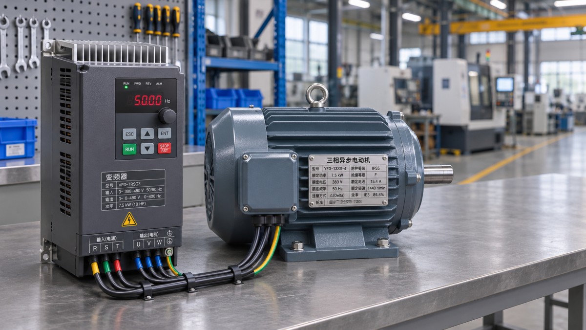
Catalog power ratings assume particular motors and operating conditions. Motors with unusual efficiency, power factor, pole count, or voltage can draw more current than the catalog’s corresponding power category suggests. Current remains the more direct comparison, provided the drive’s rating and the motor’s nameplate refer to compatible operating conditions.
Match the drive rating to the load
A drive’s continuous current rating does not describe its entire capability. Most drives also specify a temporary overload current and a permitted duration, often with a required recovery interval. Compare the complete duty cycle with that rating: magnitude, duration, repetition, and the load carried between overloads all matter.
Normal-duty and heavy-duty labels are useful only when read with their published current ratings. The same drive can have different continuous and overload ratings under each duty classification. Select the appropriate rating before comparing it with the motor; do not take the higher continuous current from one classification and the greater overload allowance from another.
Load behavior also changes with process conditions. A conveyor that starts empty places a different demand on the drive from one that must restart while fully loaded. A pump handling a more viscous fluid or a fan operating beyond its design speed can require more torque than expected. Use the most demanding credible operating condition, not just the typical steady-state point.
Account for acceleration, starting torque, and stopping
Acceleration requires torque to overcome both the driven load and the inertia of the motor and machinery. A short acceleration ramp increases the torque and current required. If a proposed drive cannot meet the starting duty, extending the ramp may be sufficient where the process allows it. Otherwise, compare a higher drive rating, a different control mode, or a revised mechanical arrangement.
High-inertia loads deserve particular attention because their acceleration current can last longer than the drive’s short-term overload rating. Confirm that the available overload is sustained for the required time and can be repeated at the planned starting frequency. A peak current figure alone does not establish that the complete acceleration cycle is permissible.
At low speed, a heavily loaded machine may need accurate torque control or position feedback. Verify the drive’s low-speed performance with the selected motor and control method. The ability to command a low frequency does not by itself prove that the system can produce the required torque continuously at that speed.
Deceleration introduces a separate constraint. An overhauling load or a high-inertia machine can return energy to the drive and raise its DC bus voltage. A longer stopping time may reduce this demand. Where the process requires faster stops or sustained overhauling operation, assess the drive’s braking or regenerative options and size the associated equipment for the actual energy and duty cycle. A larger motor-current rating alone does not establish adequate braking capacity.
Apply derating before finalizing the frame size
Drive output ratings are stated for specified conditions. Elevated ambient temperature, high altitude, limited ventilation, enclosure heat buildup, switching frequency, and certain supply arrangements can reduce the allowable output current. Apply the manufacturer’s instructions for the exact drive and installation; derating rules are not interchangeable across product families.
For example, assume a motor nameplate specifies 18 A at the intended voltage. A candidate drive rated at 20 A continuous would initially appear sufficient. If the applicable installation instructions reduce its permitted continuous output to 17 A, it no longer covers the motor’s rated current. The next suitable drive must satisfy the continuous-current requirement after all applicable derating, as well as the overload duty.
Do not assume that every derating factor can simply be multiplied or added: follow the manufacturer’s method when several conditions apply together. Also distinguish between ambient temperature outside an enclosure and the temperature immediately around the drive. Other heat-producing components and restricted airflow can make the latter higher.
Increasing the switching frequency can reduce audible motor noise, but it also increases drive losses and may lower the permitted current. Establish the intended switching setting before treating a catalog current rating as final.
Evaluate the motor across its speed range
A motor’s nameplate current and power describe rated conditions. The application must also be feasible at the speeds where it will operate. Below base speed, a motor with a shaft-mounted fan receives less cooling airflow. If it must deliver substantial torque for long periods at low speed, review its thermal capability and consider independent cooling or a motor intended for that duty. An oversized inverter cannot remove heat from the motor.
Above base speed, the drive is constrained by available output voltage. As frequency rises beyond the point where rated voltage is reached, the available continuous torque generally falls. Confirm that the load’s torque demand remains within the motor’s capability throughout the overspeed range, and verify the mechanical speed limits of the motor and driven equipment. A centrifugal load can become especially demanding at elevated speed.
Enter the correct motor nameplate parameters into the drive and set the motor thermal protection as directed by the equipment instructions. The drive’s own protection guards the inverter; motor protection must reflect the actual motor and its cooling conditions. Where close thermal supervision is needed, use compatible motor temperature sensing if supported by the drive and motor.
Consider the output circuit and control arrangement
Long motor cables, output filters, and motor insulation affect the complete selection. Fast voltage transitions and cable reflections can increase stress at the motor terminals, particularly with long leads. Consult the drive and motor documentation for permitted cable length and any need for an output reactor, voltage-limiting filter, or sine-wave filter. Include the filter’s current rating, voltage drop, losses, and installation requirements in the design.
For an existing motor, verify its suitability for inverter operation and its insulation condition. Bearing currents can also require attention in some arrangements; assess mitigation with the motor and drive documentation rather than assuming that a larger drive resolves the issue.
If one inverter supplies multiple motors, add the expected simultaneous motor currents and allow for the actual starting and operating duty. Individual motor overload protection is needed because a single drive cannot necessarily detect an overload in one motor while the combined current remains acceptable. Motor switching on the drive output also requires an arrangement expressly supported by the drive manufacturer; connecting or disconnecting a motor while the output is energized can cause trips or equipment damage.
Finally, confirm the control and protection functions that affect operation: required speed feedback, stopping behavior, input and output signals, and any safety-related functions specified for the machine. Record the motor data, load duty, derating conditions, and selected drive ratings together so that a later change in cable length, enclosure temperature, or operating cycle can be evaluated against the original sizing basis.
 How is resale changing the UK apparel and fashion market?Explore how resale is reshaping apparel and fashion in UK markets, from shifting customer demand to pricing, sourcing and opportunities for brands.
 China's Trade Reaches 44.81 Trillion Yuan in First 10 Months, Up 20%China's trade reportedly reached 44.81 trillion yuan in the first 10 months, up 20%. Explore the implications for sourcing, technology exports and ASEAN markets.
 China Extends Pause on 24% US Tariff as US Extends Product ExclusionsChina-US tariffs: China extends its 24% tariff pause while the US extends 178 product exclusions. Discover what the measures mean for trade costs and planning.
 How to verify a mass production supplier’s capacityVerify a mass production supplier’s true capacity with practical checks for production records, available resources, quality controls and delivery readiness.
 He Lifeng Holds Trade Video Call with US Treasury Secretary and Trade RepresentativeHe Lifeng discusses China-US trade restrictions with US officials. Explore what the call could mean for exporters, buyers and supply chains.
 U.S. Trade Deficit Narrows to $105 Billion in September 2026U.S. trade deficit narrowed to $105 billion in September 2026 as exports rose 1.9%. Explore what the latest figures reveal about trade flows.
 How to verify international trade intelligence updatesVerify international trade intelligence updates with practical checks for sources, regulations, trade data, and disruptions. Turn complex claims into reliable insights.
 How investors can assess cyclicality in the manufacturing industryManufacturing industry analysis for investors: learn to assess cyclical demand, cash flow and downside risks to make more informed investment decisions.
 US ISM Manufacturing PMI Rises to 55.5% in October, Beating ForecastsUS ISM Manufacturing PMI rose to 55.5% in October 2026, beating forecasts. Explore what stronger orders and production could mean for manufacturers.
 China Manufacturing PMI Falls to 49.3 in OctoberChina manufacturing PMI fell to 49.3 in October, signaling renewed contraction. Explore the role of weak export orders and domestic demand.
 Can you trust flexible packaging market intelligence forecasts?Can you trust flexible packaging market intelligence forecasts? Learn how to verify sources, challenge assumptions, and assess demand before making costly investment or sourcing decisions.
 When is supply chain disruption management consulting worth the cost?When is supply chain disruption management consulting worth the cost? Learn how to compare fees, avoidable losses, and recovery options to make a confident investment decision.
 How to use macroeconomic analysis to forecast industrial demandApply an industrial macro analysis methodology to forecast demand, interpret economic signals, and plan inventory and capacity. Discover practical steps for smarter business decisions.
 How to assess Singapore suppliers with global supply chain intelligenceExplore international supply chain intelligence Singapore buyers can use to verify suppliers, assess capabilities and delivery risks, and make confident sourcing decisions.
 Which macroeconomic indicators help forecast U.S. industrial demand?Explore industrial macro analysis USA decision-makers can use to forecast demand. Track new orders, inventories, and credit signals to sharpen procurement and capacity decisions.
 Can a food processing manufacturer meet your small-batch needs?Can a food processing manufacturer meet your small-batch needs? Discover how to assess minimum orders, costs, packaging, and safety to choose the right partner for your launch.
 How to verify sourcing intelligence data before selecting suppliersVerify sourcing intelligence data before choosing suppliers. Learn how to check company records, certifications, and capacity to reduce procurement risk and build a reliable shortlist.
 How to use supplier risk analysis to spot financial warning signsUse supplier risk analysis to spot cash flow pressure, debt risks, and delivery warning signs. Learn practical steps to reduce exposure and protect supply continuity.
 When dual sourcing makes sense in a sourcing strategy for manufacturersSourcing strategy for manufacturers: learn when dual sourcing strengthens supply continuity, reduces disruption risk, and protects production without adding unnecessary complexity.
 How bulk commodities pricing affects long-term supply contractsBulk commodities pricing shapes long-term supply contracts through index rules, freight, quality, volume, and currency risk. Explore strategies for resilient costs and supply security.
 Which global manufacturing trends by sector matter most for sourcing plans?Global manufacturing trends by sector: identify sourcing risks, supplier resilience, compliance demands, and cost drivers to build smarter, more reliable procurement plans.

















Global Trade Insights & Industry
Our mission is to empower global exporters and importers with data-driven insights that foster strategic growth.
Search News
Popular Tags
Industry Overview
The global commercial kitchen equipment market is projected to reach $112 billion by 2027. Driven by urbanization, the rise of e-commerce food delivery, and strict hygiene regulations.