

How precision engineering reduces tolerance-related failures in assemblies
Tolerance-related failures rarely announce themselves as a single dramatic defect. More often, they appear as an assembly that only fits after force is applied, a bearing that sits slightly off-axis, a gasket that leaks after thermal cycling, or a wiring harness that cannot be routed without strain. Each individual part may look acceptable on a bench. The failure emerges when real parts, produced in different batches or facilities, must work together.
That is why precision engineering is not simply about making every dimension smaller or tighter. It is the disciplined process of translating functional intent into manufacturable requirements, then proving that the production and inspection system can repeatedly meet them. For technical evaluators, this distinction matters. A supplier can quote a narrow dimensional tolerance and still create assembly risk if datums are unclear, measurement practices differ, process capability is unstable, or critical interfaces are not controlled through the full supply chain.
Why assemblies fail when individual parts appear compliant
An assembly is a system of relationships rather than a collection of independent dimensions. A shaft diameter, housing bore, mounting face, hole position, flatness requirement, and surface condition may all influence the same functional outcome. When these characteristics are evaluated separately, teams can miss the way variation accumulates.
Consider a simple bolted interface. A plate may have hole diameters within specification, while the mating bracket has its holes within specification as well. Yet if the hole patterns are located from inconsistent reference features, the bolts may not enter freely. The issue is not necessarily the hole size. It is the relationship between the hole pattern, the functional datum faces, and the assembly sequence.
This is commonly described as tolerance stack-up. In practice, it is more nuanced than adding the maximum variation of every dimension on a drawing. Some variations are statistically distributed; others are directional, linked to a process, or amplified by fixturing and handling. A machined component may be repeatable within one setup but shift after it is removed and re-clamped. A molded part can change shape as it cools. A welded frame may meet nominal dimensions before stress relief but move afterward.
The technical question is therefore not “Are the parts in tolerance?” It is “Will the assembled system meet its functional condition under realistic manufacturing, installation, and operating conditions?” Precision engineering creates a way to answer that question before defective assemblies reach the line or the customer.
Precision begins with functional datums, not tighter numbers
One of the most expensive mistakes in component sourcing is responding to a fit problem by tightening every visible tolerance. This may increase machining time, inspection cost, scrap exposure, and supplier lead time without correcting the actual source of failure.
A better starting point is to identify the features that locate the part in its working environment. These are the functional datums: the surfaces, axes, bores, pins, or interfaces that establish how a component is positioned during assembly and use. A drawing datum that is convenient for machining but unrelated to the real assembly condition can create misleading inspection results. The part may pass inspection in a controlled fixture and still misalign in the product.
For example, in a pump or valve assembly, the mounting face and bore axis may be more functionally important than several exterior dimensions. In an electronics enclosure, connector alignment and PCB mounting points often govern whether final assembly proceeds smoothly. In a battery enclosure or structural module, the relationship between sealing surfaces, fastener locations, and locating pins may be more critical than the dimensions of non-mating outer panels.
Good precision engineering makes these priorities explicit. Geometric dimensioning and tolerancing can be useful when correctly applied because it controls orientation, location, runout, profile, and form in relation to defined datums. Standards such as ASME Y14.5 and ISO 1101 are often referenced for this purpose, but their use should be confirmed against the contractual drawing standard, revision, and applicable market requirements. Mixing conventions or assuming equivalence without review can introduce ambiguity rather than remove it.
Tolerance stack-up should reflect the actual assembly path
A meaningful stack-up analysis follows the path through which parts locate one another. It accounts for the dimensions and geometric controls that affect clearance, engagement, alignment, preload, sealing, or motion. It should also reflect how the product is assembled. A component constrained by two dowel pins behaves differently from one located by a bore and a shoulder. A part installed after flexible cables, insulation layers, coatings, or gaskets have been added may see a different effective condition from the bare-metal design model.
Worst-case analysis remains appropriate where failure is unacceptable or no adjustment is possible: safety-related interfaces, non-serviceable assemblies, tightly controlled medical or electrical connections, and certain aerospace or energy applications may require it. But it can be overly conservative for high-volume processes with known, stable variation. Statistical methods may provide a more realistic picture when process data is credible and the underlying distributions have been reviewed rather than assumed.
The choice is an engineering and risk decision, not a spreadsheet preference. A technical evaluator should ask what happens at the extreme condition, whether adjustment is available, and whether a field failure can be detected before operation. These answers determine how much margin the assembly genuinely needs.
The process must be capable, not merely theoretically capable
A drawing tolerance is a requirement, not evidence that a process can achieve it economically and repeatedly. The gap between those two ideas is where many supplier disputes begin. A first article may be accepted because an experienced operator selects tools carefully, takes extra measurements, and makes manual adjustments. That does not prove production capability across shifts, machines, material lots, or tool-life cycles.
Precision engineering connects the design requirement to the production route. For a CNC-machined part, this may involve machine accuracy, fixture rigidity, cutting strategy, tool wear management, thermal behavior, and the number of setups. For injection-molded components, gate location, shrinkage behavior, mold wear, material moisture, and post-molding conditioning can affect critical features. For fabricated or welded structures, sequence, heat input, clamping, and downstream straightening may matter more than nominal cutting accuracy.
This is why process capability discussions should focus on critical-to-function features rather than a generic promise that “all dimensions will be controlled.” Depending on the project, a buyer may reasonably request capability evidence, control plans, inspection records, first-off and last-off checks, or an agreed response plan for trends approaching a limit. The appropriate evidence depends on product risk, order volume, and the maturity of the supplier relationship.
It is also worth separating machine capability from process capability. A high-end machine does not automatically create stable output. Poor datum selection, inadequate workholding, or measurement variation can defeat the advantage of excellent equipment.
Measurement disagreement is itself an assembly risk
When a supplier says a part passes and the receiving team says it fails, the immediate instinct is often to remeasure the component. That is necessary, but it may not be enough. The two parties may be using different datum interpretations, probing strategies, clamping conditions, temperature assumptions, sampling plans, or gauge resolution. A thin stamped bracket can measure differently when supported in a fixture than when resting freely on a surface plate. A soft polymer feature can be affected by contact force. A coated bore may be evaluated before or after finishing, with very different implications for fit.
For critical interfaces, the measurement method should be part of the technical package. Coordinate measuring machines, dedicated functional gauges, optical systems, air gauges, and conventional instruments all have suitable applications, but they do not answer the same question. A functional gauge can be especially valuable when the real concern is assembly acceptance rather than the isolated measurement of multiple coordinates.
Technical evaluators should also look for an appropriate measurement-system review. The purpose is not paperwork for its own sake. It is to establish whether the gauge and method can distinguish meaningful part variation from measurement noise. Without that confidence, apparent process trends and acceptance decisions can be misleading.
Cross-border sourcing adds variation beyond the part drawing
In global supply chains, tolerance management has a commercial dimension as well as an engineering one. A component may move between design teams, contract manufacturers, finishing providers, inspection houses, and final assembly sites. Every handoff creates potential for a drawing revision to be misunderstood, a material substitution to affect stability, or a coating process to change a fit condition.
The risk is particularly visible when suppliers quote against incomplete documentation. A nominal CAD model without clear datum logic, unspecified surface requirements, or vague notes such as “fit as required” invites different interpretations. The cheapest quote can become the most expensive option if production begins before those ambiguities are resolved.
For procurement and technical review teams, useful supplier questions include:
- Which features are considered critical to assembly function, and how are they controlled in production?
- What datums are used for machining and inspection, and do they match the functional assembly condition?
- Will coating, heat treatment, welding, molding shrinkage, or finishing alter the stated dimensions?
- What inspection method will be used for the key interfaces, and can results be reported in an agreed format?
- How are drawing revisions, nonconformities, and approved process changes communicated across sites?
These questions are more revealing than a broad statement about quality control. They show whether the supplier understands the assembly as a functional system or views the work only as a list of independent dimensions.
Where technical evaluation should focus before production release
The most effective reviews happen before tooling is committed and before a purchase order turns assumptions into schedule pressure. Start with the interfaces that cannot be corrected later: press fits, seals, rotating elements, safety enclosures, precision optical alignments, electrical connectors, and parts that become inaccessible after final assembly. Then identify the variation sources that can shift those interfaces: manufacturing, material condition, finishing, transport damage, installation force, temperature, and service loading.
Assembly trials should be planned to reveal boundary conditions, not merely demonstrate that hand-selected prototypes fit once. When feasible, trials using parts from different production lots or suppliers can expose stack-up sensitivity earlier. A design that only assembles with matched components may be unsuitable for normal production unless matching is an intentional and controlled requirement.
It is equally important to distinguish a true design problem from a supplier process problem. If the tolerance zone is functionally correct but one process drifts, the response may be improved fixturing, tool management, or inspection discipline. If multiple capable suppliers struggle with the same interface, the design definition may need reconsideration. Treating every issue as a supplier-quality failure can delay the real correction.
Precision engineering is a decision framework, not a premium feature
The strongest assembly designs do not demand maximum precision everywhere. They place control where function depends on it, allow reasonable freedom where it does not, and define how compliance will be verified. This balance protects quality without making the product unnecessarily difficult to manufacture or source.
For organizations comparing suppliers across regions, the technical drawing alone is only part of the evidence. Production capability, measurement alignment, change-control discipline, logistics handling, and regulatory documentation can all influence whether a precision component arrives ready for assembly. Platforms such as Global Trade Insights & Industry Network can help teams interpret supplier-region conditions, manufacturing trends, and cross-border risks alongside the engineering requirements themselves.
The practical test is simple: can the supplier explain not only how a dimension is measured, but why that feature matters to the final assembly and how its variation is prevented from becoming a field problem? When that answer is clear, tolerance control has moved beyond inspection. It has become part of reliable product engineering.
 When an export market analysis platform can validate demand in a new marketExport market analysis platform insights help validate new-market demand through buyer fit, regulations, logistics, competition, and profitable entry conditions.
 What is driving the beauty and personal care market in the USA?Beauty and personal care in USA is driven by targeted solutions, selective premiumization, digital discovery, clean-label trust, diverse needs, and compliance. Explore key growth opportunities.
 How trade flow monitoring reports reveal changing regional demandTrade flow monitoring reports reveal changing regional demand through import volumes, sourcing shifts, product mix, logistics signals, and regulatory trends. Explore actionable market insights.
 How international market intelligence for investors reduces market-entry riskInternational market intelligence for investors reduces market-entry risk by validating demand, regulations, logistics, and competition before capital is committed.
 How international sourcing intelligence helps identify supplier risk earlyInternational sourcing intelligence helps businesses spot supplier risks early, protect supply continuity, and make smarter global procurement decisions.
 How trade data aggregation analytics reveals emerging supplier marketsTrade data aggregation analytics reveals emerging supplier markets through export trends, input flows, logistics, and regulatory signals. Discover smarter sourcing insights.
 What industrial cluster monitoring in Vietnam reveals about site riskIndustrial cluster monitoring Vietnam reveals hidden site risks across labor, utilities, logistics, compliance, and supplier dependencies. Make smarter sourcing and expansion decisions.
 Food Technology Trends Reshaping Shelf Life, Safety, and Product InnovationFood technology is reshaping shelf life, safety, and innovation. Discover the trends helping food businesses cut risk, improve compliance, and unlock stronger global market growth.
 How electronics manufacturing services are changing with low-volume demandElectronics manufacturing services are evolving fast with low-volume demand. Learn how agile EMS partners improve flexibility, compliance, sourcing resilience, and speed to market.
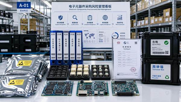
 How Can Buyers Reduce Procurement Risks for Electronic Components?How to reduce procurement risks for electronic components: learn how buyers assess traceability, lead times, compliance, and supplier types to avoid costly sourcing mistakes.
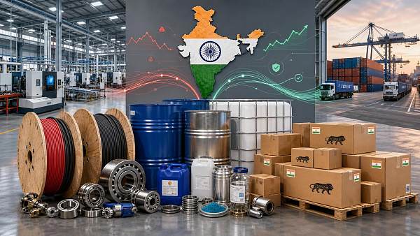
 What Sourcing Intelligence India Reveals About Supplier Risk and Cost ShiftsSourcing intelligence India reveals hidden supplier risk, compliance gaps, logistics pressure, and real cost shifts—helping buyers compare vendors smarter and source with more confidence.
 Fashion Trends 2026: Which Materials, Colors, and Silhouettes Are Gaining Ground?Fashion trends 2026 spotlight tactile fabrics, mineral colors, and controlled volume. Explore the materials, shades, and silhouettes shaping smarter, more wearable style.
 Smart Device Market Outlook: Key Growth Drivers, Segments, and Business OpportunitiesSmart device market trends are shifting toward system value, industrial demand, and resilient supply chains. Explore key growth drivers, high-potential segments, and business opportunities.
 How Global Trade Intelligence Services Help B2B Firms Evaluate Markets and SuppliersGlobal trade intelligence services help B2B firms compare suppliers, assess market potential, and uncover compliance, logistics, and pricing risks before costly decisions are made.
 Manufacturing Sector Updates for Investors: What Signals Matter Most in 2025?Manufacturing sector updates for investors in 2025: track orders, margins, supply chains, regulation, and exports to spot resilient manufacturers and smarter investment signals.
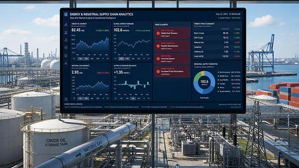
 How Energy Market Intelligence Helps Businesses Track Price Risks and Demand ShiftsEnergy market intelligence helps businesses spot price risks, demand shifts, and supply pressure early—improving procurement, resilience, and faster strategic decisions.
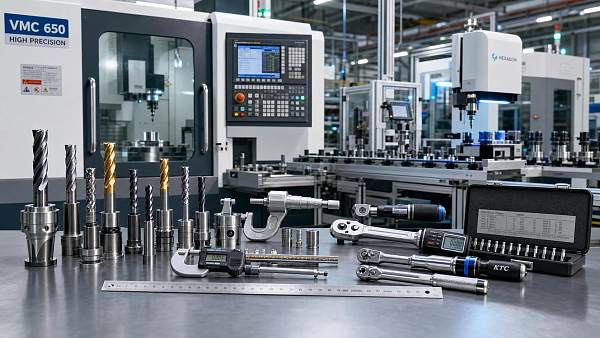
 Precision Hardware Tools Market: Key Demand Drivers, Segments, and Growth OutlookPrecision hardware tools market trends are reshaping sourcing, compliance, and automation. Explore key demand drivers, segment shifts, regional supply patterns, and growth opportunities.
 How to Use Customs Import Data to Find Buyers, Track Competitors, and Spot Demand?Customs import data helps you find real buyers, track competitors, and spot demand shifts early. Learn practical ways to turn trade records into smarter global business decisions.
 Manufacturing Cost Analysis: 8 Cost Drivers That Change Your Unit PriceManufacturing cost analysis explained through 8 key cost drivers that impact unit price, supplier stability, and margins—learn how to compare quotes smarter and reduce sourcing risk.
 Industrial Market Realities: What Buyers Should Check Before Comparing Supplier QuotesIndustrial market realities shape every supplier quote beyond unit price. Learn what to check on compliance, lead times, logistics, and hidden cost risks before comparing offers.
 Beverage Production Line Planning: Key Equipment, Capacity, and Hygiene RequirementsBeverage production line planning made practical: discover key equipment, real capacity sizing, and hygiene requirements to improve efficiency, safety, and long-term plant performance.













Global Trade Insights & Industry
Our mission is to empower global exporters and importers with data-driven insights that foster strategic growth.
Search News
Popular Tags
Industry Overview
The global commercial kitchen equipment market is projected to reach $112 billion by 2027. Driven by urbanization, the rise of e-commerce food delivery, and strict hygiene regulations.