

How power quality monitoring helps identify the source of voltage sags
How Power Quality Monitoring Helps Identify the Source of Voltage Sags
Voltage sags can disrupt production, damage sensitive equipment, and create costly uncertainty across industrial operations. Power quality monitoring provides the evidence technical evaluators need to identify likely sag sources.
The essential question is not simply whether a voltage sag occurred. Evaluators need to determine where it originated, how it propagated, which assets were exposed, and whether recurrence is likely.
A properly designed monitoring program turns isolated complaints into time-synchronized electrical evidence. It helps teams distinguish internal load events from utility disturbances, switching operations, wiring faults, and distribution weaknesses.
For technical assessment teams, the value lies in defensible diagnosis. Monitoring data supports corrective investment decisions, supplier discussions, maintenance priorities, equipment specifications, and risk assessments for critical facilities.
Why Identifying the Sag Source Matters
A voltage sag is a short-duration reduction in RMS voltage, commonly caused by faults, motor starts, transformer energization, feeder events, or upstream utility problems.
Although a sag may last only milliseconds or seconds, sensitive equipment can respond immediately. Drives may trip, PLCs may reset, contactors may drop out, and process controls may lose synchronization.
Without source identification, organizations often replace equipment that was not defective. They may install expensive conditioning devices while leaving the actual electrical disturbance unchanged.
Power quality monitoring reduces this uncertainty by capturing event magnitude, duration, waveform behavior, phase involvement, and timing. These details reveal patterns that ordinary maintenance observations cannot provide.
The source also determines responsibility. An internal motor-starting issue belongs to plant engineering, while a utility feeder fault may require coordination with the network operator.
For evaluators comparing sites, suppliers, or production partners, sag performance is an operational resilience indicator. Repeated disturbances can signal weak electrical design or inadequate maintenance control.
Reliable diagnosis protects both capital expenditure and production continuity. It allows technical teams to select solutions proportionate to the event mechanism rather than reacting to symptoms.
The goal is therefore not zero recorded events. The goal is a clear, evidence-based explanation of which events create risk and what practical action will reduce that risk.
What Power Quality Monitoring Records During a Sag
Modern power quality monitoring records voltage values continuously and captures high-resolution event data when predefined thresholds are crossed. This provides more context than periodic meter readings.
The most useful records include sag depth, duration, affected phases, phase-angle changes, waveform shape, frequency behavior, current response, and precise event timestamps.
Sag depth describes how far voltage falls below nominal conditions. A drop to 70 percent of nominal voltage generally creates more equipment risk than a shallow reduction.
Duration matters because different devices have different immunity limits. Some controls tolerate a brief interruption, while others trip during a sag lasting only a few cycles.
Phase information is especially valuable. A three-phase balanced sag may suggest an upstream transmission or utility event, while an unbalanced event can indicate a local fault.
Current data helps determine whether the facility caused the disturbance. A large simultaneous current increase may point to motor acceleration, transformer inrush, welding equipment, or fault current.
Waveform captures can reveal switching transients, harmonic distortion, or notching around the event. These signals help separate voltage sag mechanisms that otherwise look similar in summary reports.
Accurate timestamps are critical. When monitors across different electrical locations use synchronized clocks, event sequence analysis becomes possible instead of relying on operator recollection.
Use Monitoring Locations to Trace Event Direction
Monitor placement is often the deciding factor in source identification. A single device at the service entrance can detect a sag, but usually cannot prove its origin.
Technical evaluators should monitor the utility incomer, major distribution boards, critical process buses, and large nonlinear or high-inrush loads where practical.
If a sag appears at the incoming service and downstream panels at the same time, the source is more likely upstream of the facility.
If the voltage is stable at the incomer but falls at one internal distribution board, the disturbance likely originates within the plant distribution system.
Comparing severity between locations provides another useful clue. A sag that becomes deeper downstream may indicate feeder impedance, undersized conductors, loose connections, or transformer limitations.
Current direction and phase relationships can improve the conclusion. A sharp load-current increase before the voltage drop usually supports an internal source rather than an external utility event.
Large facilities should avoid assuming every event has one cause. Separate production areas can experience different sag mechanisms because of local loads, transformers, and feeder arrangements.
A monitoring map should follow the one-line diagram. This makes event interpretation easier and ensures every recorded disturbance can be linked to a defined electrical path.
How Event Signatures Point to Internal Causes
Internal voltage sags frequently occur when equipment demands a sudden and substantial current. Common examples include direct-on-line motor starts, compressor starts, and large pump acceleration.
Motor-starting sags often show a voltage decline with a corresponding high current inrush. The event generally appears strongest near the motor feeder and nearby distribution bus.
Transformer energization can produce a similar initial voltage reduction. However, waveform records may show inrush characteristics, including asymmetrical current and temporary harmonic-rich behavior.
Arc furnaces, welders, crushers, and cyclical industrial loads can create repeated sag patterns. Their event timing often aligns closely with operating schedules or production cycles.
Internal faults may cause deeper and more abrupt sags. Protective devices, breaker logs, relay records, and monitor timestamps should be reviewed together after these events.
Loose terminations, degraded cable joints, overloaded feeders, and poor grounding do not always create dramatic events. They can nevertheless worsen local voltage response under normal load changes.
Power quality monitoring should be correlated with operational data. Production historians, motor control logs, and maintenance work orders can confirm whether monitored signatures match equipment activity.
When internal sources are confirmed, solutions may include soft starters, variable-frequency drives, staggered starts, transformer upgrades, feeder improvements, or revised load-management practices.
How Monitoring Separates Utility and Upstream Disturbances
Utility-originated voltage sags often result from faults on nearby distribution lines, transmission circuits, substations, weather-exposed infrastructure, or protective switching operations.
These events may appear simultaneously across multiple facility meters, particularly at the service entrance. Internal current usually does not rise enough to explain the voltage reduction.
A balanced three-phase sag can indicate a three-phase upstream fault, although evaluators should avoid treating this pattern alone as definitive proof of utility responsibility.
Single-line-to-ground and line-to-line faults often produce unbalanced sags. One or two phases may experience larger reductions, creating a recognizable voltage pattern across monitors.
Comparing facility data with utility event records is valuable. A synchronized timestamp, matching duration, and compatible fault description create a stronger evidence trail.
Multiple facilities in the same industrial area may experience the same event. Where available, regional monitoring data can help determine whether a disturbance affected a wider network.
Utility events are not necessarily signs of poor service quality. However, frequent or severe occurrences should trigger discussions about feeder exposure, protection settings, and service alternatives.
Technical teams should document the impact rather than only the event count. Utility conversations are more productive when evidence links sag characteristics to specific equipment trips or production losses.
Interpret Sag Data Against Equipment Immunity
Identifying the source is important, but source data must be connected to equipment tolerance. A recorded sag only becomes a business concern when it exceeds process immunity.
Different equipment responds differently to the same voltage event. Contactors, programmable controllers, variable-speed drives, servers, sensors, and process instruments have distinct ride-through capabilities.
Voltage tolerance curves provide a structured comparison method. They help evaluators determine whether an event was severe enough to reasonably explain a trip or reset.
Monitoring reports should identify the affected equipment, its nominal supply voltage, protection configuration, and expected voltage ride-through performance at the recorded duration.
Many investigations fail because teams rely on nominal ratings alone. Equipment may be technically rated for a voltage range but still have vulnerable control power supplies.
Control circuits deserve special attention. A momentary sag on a higher-voltage motor bus can cause low-voltage control devices to drop out before motor protection operates.
Critical systems may require event-triggered correlation. Recording alarm histories, PLC fault codes, network interruptions, and process deviations alongside electrical events improves diagnosis.
This analysis prevents overengineering. A facility may not need plant-wide conditioning if only one control circuit lacks adequate ride-through capability during a recurring sag.
Build a Monitoring Plan That Produces Defensible Findings
A useful power quality monitoring program begins with an investigation objective. Teams should define whether they are studying nuisance trips, supplier-site reliability, utility performance, or expansion risk.
Start with a current one-line diagram and identify critical loads, incoming supply points, transformers, major feeders, protective devices, and known disturbance locations.
Select instruments that capture sag events at appropriate resolution and comply with relevant measurement standards. Basic energy meters may not provide enough waveform or timing detail.
Establish consistent trigger settings, voltage references, and time synchronization across all monitors. Inconsistent configuration can make cross-location comparison unreliable or misleading.
Monitoring duration should reflect operating conditions. A short study may miss infrequent utility faults, while a longer campaign can reveal seasonal, weather-related, or production-linked patterns.
Collect operational context during the study. Record equipment starts, shift changes, process batches, maintenance activities, switching operations, and reported control-system failures.
Review events by severity and operational impact rather than reviewing every waveform in isolation. Grouping similar signatures often reveals recurring mechanisms faster than chronological inspection.
The final report should state confidence levels and limitations. Where evidence is incomplete, evaluators should recommend additional monitor locations or a longer observation period.
Turn Findings Into Corrective Actions and Procurement Decisions
Once the likely source is identified, corrective action should address both the electrical cause and the affected equipment’s vulnerability. Either side alone may leave residual risk.
For internal load-related sags, evaluate starting methods, load sequencing, feeder impedance, transformer capacity, and the location of sensitive control equipment.
For distribution weaknesses, inspect connections, conductor sizing, voltage regulation, protection coordination, transformer loading, and circuit separation between sensitive and disruptive loads.
For utility-related events, assess ride-through upgrades, uninterruptible power supplies, dynamic voltage restorers, alternative feeds, and contractual service-quality discussions where relevant.
Technical evaluators should compare remedies using event frequency, expected downtime reduction, maintenance impact, installation complexity, and total cost of ownership.
Monitoring evidence also improves procurement specifications. New machinery can be required to meet defined voltage immunity levels, support controlled starting, and provide event logs.
When assessing external manufacturers or industrial partners, ask whether they monitor power quality, maintain event records, and understand the reliability of their electrical infrastructure.
For global supply chains, electrical resilience can influence delivery risk. Facilities with recurring unexplained trips may face avoidable capacity losses during high-demand production periods.
Conclusion: Monitoring Creates a Clearer Basis for Electrical Risk Decisions
Power quality monitoring helps technical evaluators move from assumptions to evidence. It identifies when voltage sags occur, how they behave, where they intensify, and what likely caused them.
The strongest investigations combine synchronized measurements at multiple locations with current data, waveform captures, equipment logs, and a current electrical one-line diagram.
Internal loads, distribution problems, and utility events require different responses. Accurate source identification ensures corrective spending targets the actual mechanism instead of treating general symptoms.
For industrial operations and supply-chain assessments, a disciplined monitoring program strengthens reliability decisions, supports accountability, and provides a practical foundation for preventing future voltage-sag disruption.
 When dual sourcing makes sense in a sourcing strategy for manufacturersSourcing strategy for manufacturers: learn when dual sourcing strengthens supply continuity, reduces disruption risk, and protects production without adding unnecessary complexity.
 How bulk commodities pricing affects long-term supply contractsBulk commodities pricing shapes long-term supply contracts through index rules, freight, quality, volume, and currency risk. Explore strategies for resilient costs and supply security.
 Which global manufacturing trends by sector matter most for sourcing plans?Global manufacturing trends by sector: identify sourcing risks, supplier resilience, compliance demands, and cost drivers to build smarter, more reliable procurement plans.
 What industrial trade intelligence pricing should include before you subscribeIndustrial trade intelligence pricing explained: compare coverage, data quality, access rights, and workflow value before choosing a subscription that supports smarter trade decisions.
 How an industrial trade intelligence dashboard can identify new supplier marketsDiscover how an industrial trade intelligence dashboard helps identify new supplier markets by comparing capacity, landed cost, logistics resilience, and compliance risk.
 Which global market entry barriers should exporters assess first?Global market entry barriers exporters should assess first: tariffs, compliance, buyer qualification, logistics, and payment risk. Build a practical strategy for confident market entry.
 How trade data aggregation analytics can reveal emerging supplier marketsTrade data aggregation analytics reveals emerging supplier markets by connecting trade flows, capacity signals, logistics, and compliance insights for smarter sourcing decisions.
 When an export market analysis platform can validate demand in a new marketExport market analysis platform insights help validate new-market demand through buyer fit, regulations, logistics, competition, and profitable entry conditions.
 What is driving the beauty and personal care market in the USA?Beauty and personal care in USA is driven by targeted solutions, selective premiumization, digital discovery, clean-label trust, diverse needs, and compliance. Explore key growth opportunities.
 How trade flow monitoring reports reveal changing regional demandTrade flow monitoring reports reveal changing regional demand through import volumes, sourcing shifts, product mix, logistics signals, and regulatory trends. Explore actionable market insights.
 How international market intelligence for investors reduces market-entry riskInternational market intelligence for investors reduces market-entry risk by validating demand, regulations, logistics, and competition before capital is committed.
 How international sourcing intelligence helps identify supplier risk earlyInternational sourcing intelligence helps businesses spot supplier risks early, protect supply continuity, and make smarter global procurement decisions.
 How trade data aggregation analytics reveals emerging supplier marketsTrade data aggregation analytics reveals emerging supplier markets through export trends, input flows, logistics, and regulatory signals. Discover smarter sourcing insights.
 What industrial cluster monitoring in Vietnam reveals about site riskIndustrial cluster monitoring Vietnam reveals hidden site risks across labor, utilities, logistics, compliance, and supplier dependencies. Make smarter sourcing and expansion decisions.
 Food Technology Trends Reshaping Shelf Life, Safety, and Product InnovationFood technology is reshaping shelf life, safety, and innovation. Discover the trends helping food businesses cut risk, improve compliance, and unlock stronger global market growth.
 How electronics manufacturing services are changing with low-volume demandElectronics manufacturing services are evolving fast with low-volume demand. Learn how agile EMS partners improve flexibility, compliance, sourcing resilience, and speed to market.
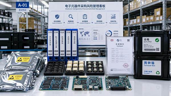
 How Can Buyers Reduce Procurement Risks for Electronic Components?How to reduce procurement risks for electronic components: learn how buyers assess traceability, lead times, compliance, and supplier types to avoid costly sourcing mistakes.
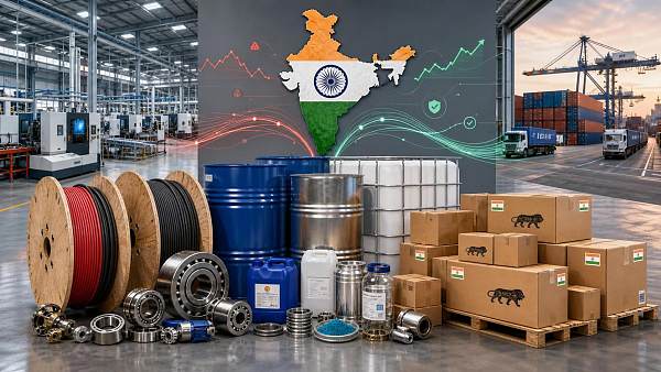
 What Sourcing Intelligence India Reveals About Supplier Risk and Cost ShiftsSourcing intelligence India reveals hidden supplier risk, compliance gaps, logistics pressure, and real cost shifts—helping buyers compare vendors smarter and source with more confidence.
 Fashion Trends 2026: Which Materials, Colors, and Silhouettes Are Gaining Ground?Fashion trends 2026 spotlight tactile fabrics, mineral colors, and controlled volume. Explore the materials, shades, and silhouettes shaping smarter, more wearable style.
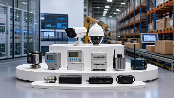
 Smart Device Market Outlook: Key Growth Drivers, Segments, and Business OpportunitiesSmart device market trends are shifting toward system value, industrial demand, and resilient supply chains. Explore key growth drivers, high-potential segments, and business opportunities.
 How Global Trade Intelligence Services Help B2B Firms Evaluate Markets and SuppliersGlobal trade intelligence services help B2B firms compare suppliers, assess market potential, and uncover compliance, logistics, and pricing risks before costly decisions are made.










Global Trade Insights & Industry
Our mission is to empower global exporters and importers with data-driven insights that foster strategic growth.
Search News
Popular Tags
Industry Overview
The global commercial kitchen equipment market is projected to reach $112 billion by 2027. Driven by urbanization, the rise of e-commerce food delivery, and strict hygiene regulations.